
Working with operating high voltage assets, following plant trips, it may be necessary to analyse protection relay fault records. The following are some tips to ensure that a fault record is triggered and aids fault finding.
Available Records from Protection Relays
Usually these will be in the form of two files:
- Event record (or sequence of events) containing time-stamped entries corresponding to relay word bits/status codes/alarms/warnings (however the protection relay manufacturer calls them).
- Oscillography. This is in the form of a COMTRADE file and contains sampled analogue data and digital channels to enable deeper analysis of the fault.
The sequence of discovering more information about a fault from a protection relay usually is:
- Look on the front screen of the relay. Typically, the trip condition, phase and max current will be displayed
- Examine the event log
- Examine the oscillography
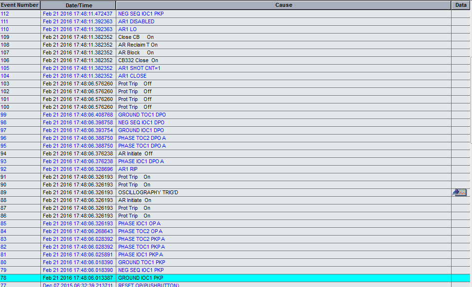
Example Extract from protection relay event log as viewed on GE’s user-friendly Enervista software.
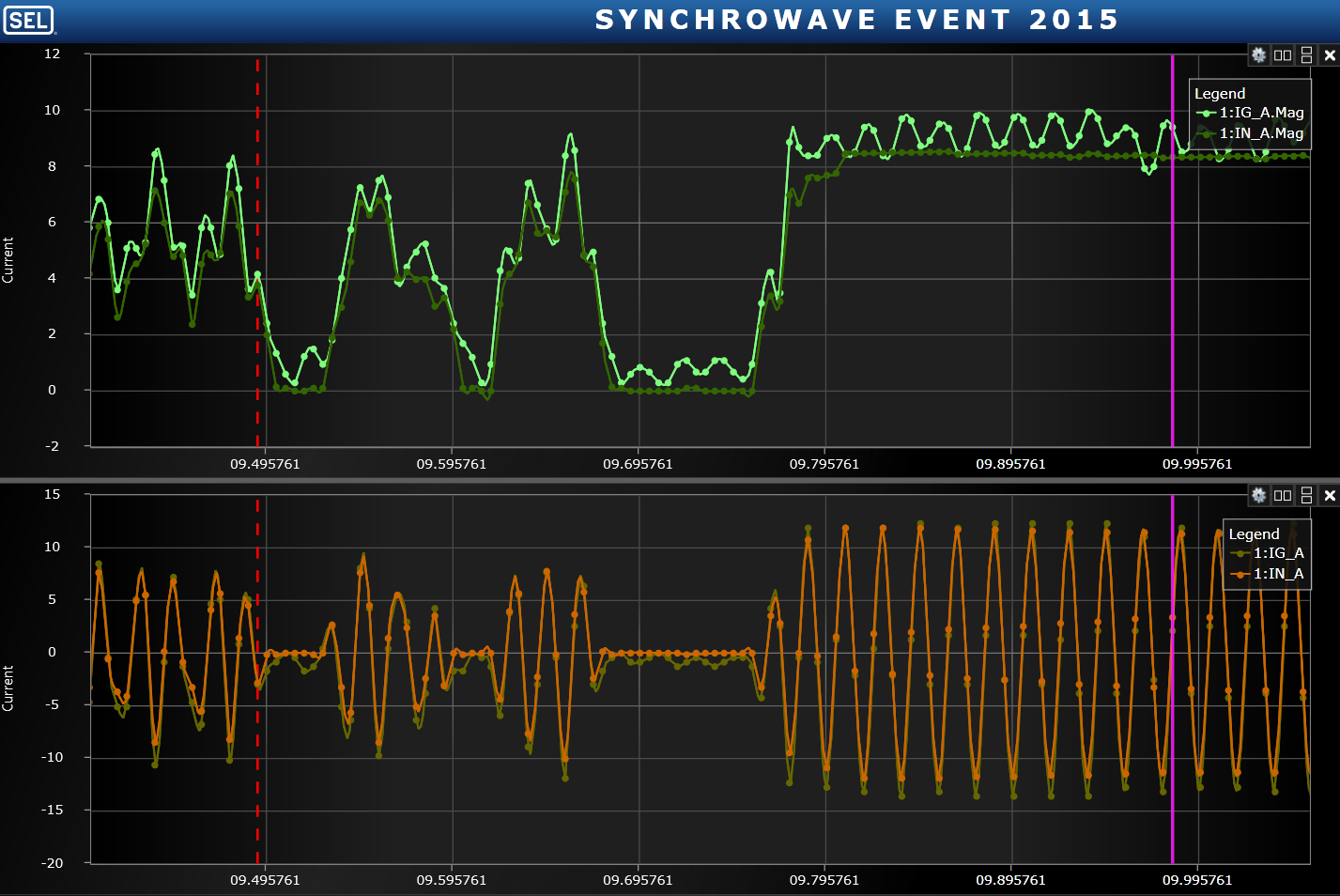
Example oscillography from a SEL-751 as viewed in SEL Synchrowave software
Recommended Protection Relay Fault Record Acceptance Checks
The following are often-overlooked aspects which aid in correct fault-finding. Some of the below items could be added to electrical specifications so that the plant is delivered in a manner that improves the chances of correctly identifying the fault.
- Ensure protection relay time synchronisation. It is difficult to retrace a fault (especially across multiple recording devices or SCADA systems) if time synchronisation is out.
- Ensure protection relay is accessible remotely. Network security must be considered, but it is a business requirement to be able to remotely analyse protection relay fault records and they cannot easily be retrieved unless the relay is connected to the site LAN and the site LAN is accessible from off-site.
- When performing secondary injection testing, download and review the generated oscillography to ensure:
a. the analogue channels are correctly named and understandable
b. the digital channels are correctly named and understandable (for example if there is an external trip from the utility via digital input 104, it aids fault-finding for this to be named EXT_UTILITY_TRIP than the default IN104.
c. Ensure that the pre- and post-trigger configuration is correct so that the whole event fits into the oscillogram. If the oscillography is not present or the entire timeframe of interest has not been captured, check the oscillography trigger logic and the transient recorder time offsets in the protection relay settings. Protection relay transient recorders are continuously recording (and overwriting). Upon the trigger condition occurring (e.g. TRIP code going high) the contents of the transient recorder are written to non-volatile memory and saved. Alter the number of cycles before and after the trigger condition (i.e. the position of the window of data to be saved) so that the most useful information is captured.
- Ensure that oscillography has been configured to trigger a recording for all the situations required. This includes trips initiated from external digital inputs, for example.
- Check that the transient recorder time offsets are suitable.
- Install software to allow downloading of fault records as well as their analysis. Do this before a power system incident occurs. Take the time to configure the relays under the substation name (with correct IP addresses etc.). Ensure that the records can be downloaded and examined in a COMTRADE file viewer so that when requested to urgently investigate a fault, this setup is already done.
- Configure the line impedance settings so that the fault locator feature will provide an estimate of fault location. This is only possible in some cases where the electrical topology suits.
For example analysis of a protection relay fault record, refer to this article examining a simultaneous earth fault on two wind farm collector groups.