
Improving Current Asymmetry on New Wind Farms
When building a new wind farm, the following actions could be taken to minimise current asymmetry:
- Evenly distribute the medium voltage wind turbine collector group phasing at the substation. Connect an equal number of collector groups with ABC, BCA and CAB phasing. Begin with the longest/largest collector groups (electrically longest – consider the higher impedance of overhead lines compared to cables). Ensure long collector groups are evenly distributed between ABC, CAB and BCA phasing. Ensure the phase rotation remains the same at each turbine – permissible configurations are ABC, BCA and CAB. Swapping two phases (e.g. ACB or BAC) will make machines spin backwards!
- Ensure sufficient cable length is left under the switchroom (where each collector group connects to the main MV bus) to allow for future phase transpositions if necessary. This is good practice anyway as it allows room to remove damaged cable in the case of MV termination failure (an inline joint can be avoided).
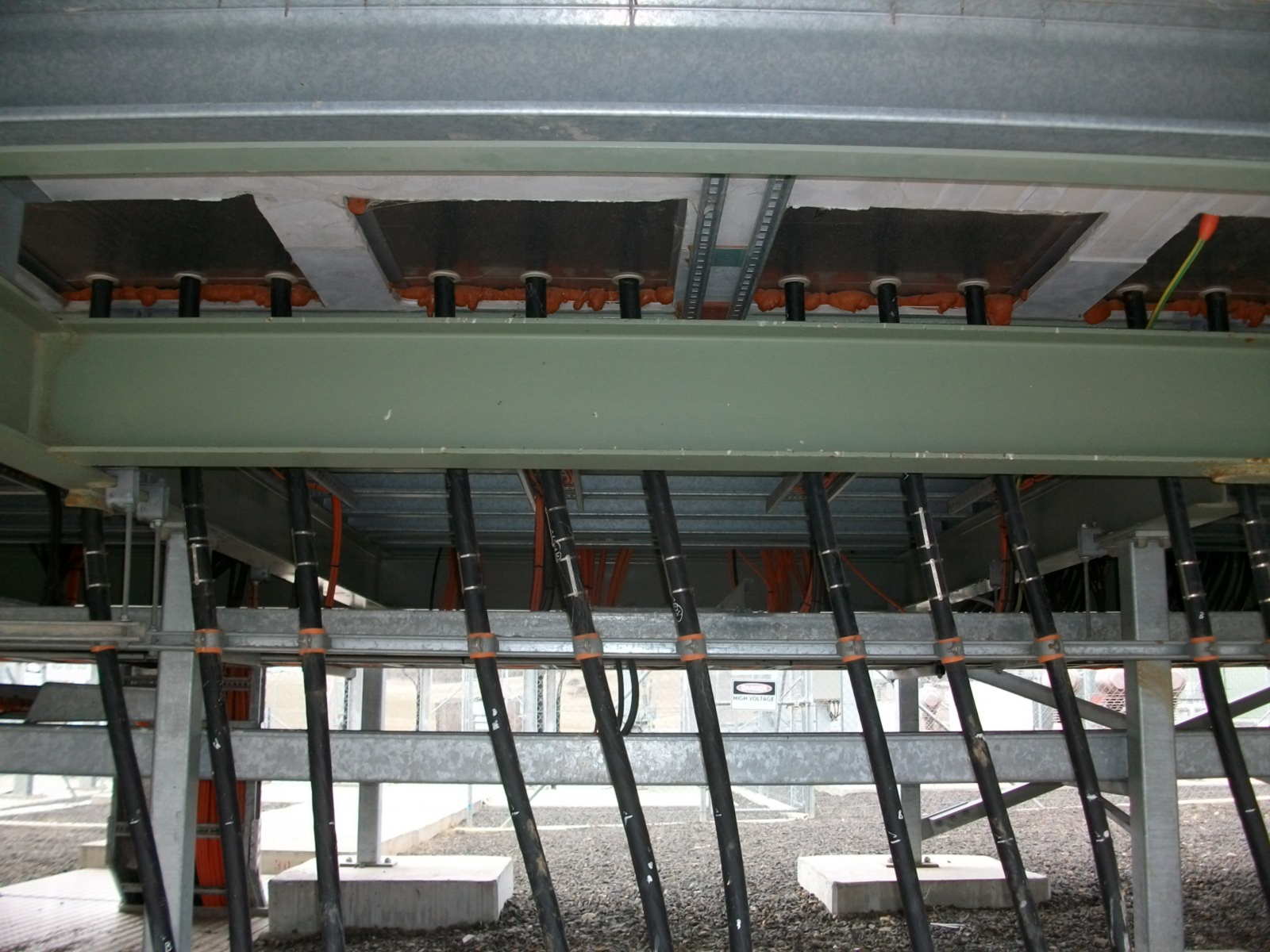
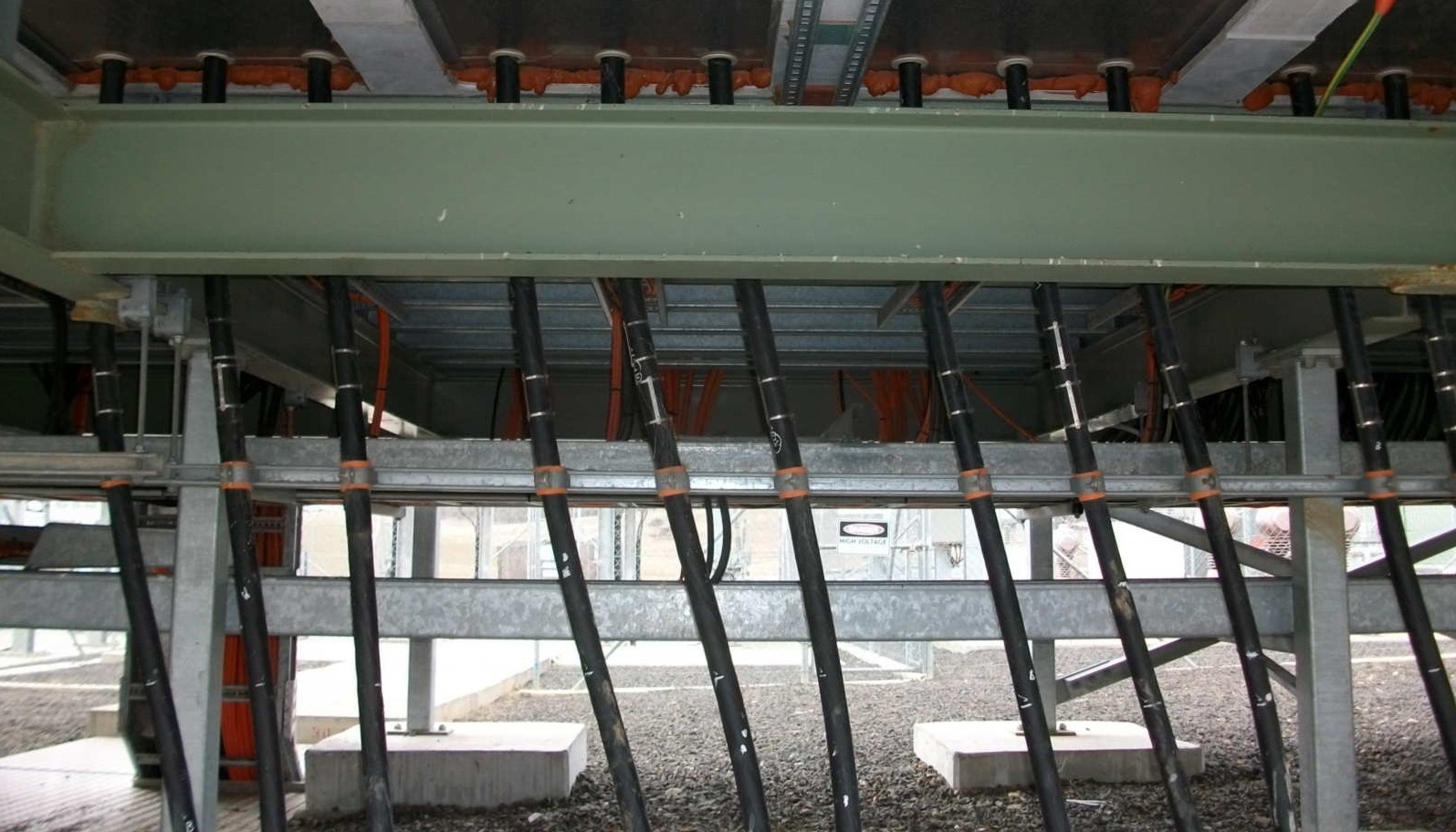
Typical 33kV collector group cabling entering switchboard at wind farm substation. Ensure during construction that sufficient length is spare (e.g. curled in cable culvert) to allow for phase transposition. This will save a lot of hassle if current imbalance issues are encountered on the wind farm. This should be normal practice anyway, as insurance against termination failures.
Note that the recommendations provided above may still result in uneven current distribution on individual collector groups, but allows entire collector groups to be transposed post-commissioning to fine-tune any remaining current imbalance at the point of connection. An alternative would be to transpose the medium voltage cable phasing at each wind turbine transformer (or MV switchgear). However this makes fine-tuning difficult because changing phasing as the collector group enters the substation may have little effect (as the phasing within any given collector group would already be quite balanced).
These recommendations only reduce current asymmetry if there are inherent impedance unbalances within the wind farm. As discussed in Part 1, impedance and voltage imbalances may arise from multiple locations – for example impedance imbalances within the wind farm may bias the current to increase on Phase B, but voltage imbalances on the transmission network may bias the current to increase on Phase A. Therefore the optimal arrangement (to reduce both voltage imbalance and current asymmetry) might be found by transposing phases such that at the medium voltage level within the wind farm, a higher current is encouraged to flow on the particular phase with highest voltage, creating more voltage drop and acting to balance the voltages.
Once the wind farm is operational, additional phase transpositions may be required to reduce current asymmetry and/or voltage imbalance at the point of connection. It may not be possible to minimise both wind turbine current asymmetry and voltage asymmetry at the point of common coupling (PCC).
Improving Current Asymmetry on Existing Wind Farms
If current asymmetry or voltage imbalance are causing problems, the below recommendations may reduce the asymmetry. Note that because there may be multiple mechanisms influencing the asymmetry, an empirical (trial and error) approach is recommended over a model-based approach.
If the asymmetry appears to stem from the grid (e.g. if the grid voltage asymmetry is high), investigate whether the utility is achieving their minimum power quality standard. If not, there may be a case to have them perform phase transpositions on their overhead lines in order to better balance the voltages. Phase transposition of the utility’s assets may not be an option. If not, try phase transpositions within the wind farm:
- Collect the following 10-minute average measurements from the wind farm SCADA system. Collect a period of at least one month prior to phase transposition:
- Current asymmetry at the wind turbine generator
- Wind Turbine current in each phase
- Active power of each wind turbine
- Wind Turbine terminal voltage
- Medium voltage rms voltage levels (phase to phase and phase to neutral could both be applicable)
- Medium voltage collector group currents in each phase
- Wind farm active power (at PCC)
- Voltage levels at PCC (phase to phase and phase to neutral)
- Current in each phase at PCC
2. Choose a collector group with many turbines and a long run of cable/overhead line between the substation and the turbines. Additionally this collector group must be cabled to allow the phasing to be transposed. Transposing at the substation is preferable. If a cause of current asymmetry is located between the substation and first turbine on the collector group (for example wind farm overhead lines) then transposition needs to be made at the substation. This shifts the impedance imbalance on that collector group from the present phase onto a different one. If transpositions cannot be made underneath the switchboard, phase transpositions performed at the MV switchgear of the first turbine on a collector group can still have positive results – refer to Part 3 for a discussion of results of phase transposition at one particular wind farm.
3. Select a phase transposition. Identify the phase with the highest current and the phase with the highest voltage (at medium voltage level). If it is possible to transpose the highest current phase onto the highest voltage phase, select this transposition. However, because unbalance may be introduced from outside of the wind farm (upstream of the proposed transposition location), results are not always as expected. Transposing two collector groups at once is an option. This way the change in asymmetry can be compared for BCA as well as CAB transpositions. However, this makes attributing any overall change at PCC more difficult to narrow down to a particular phase transposition.
4. On a low wind day perform the phase transposition(s) on the selected collector group(s).
5. After reenergising a transposed collector group but before restarting the turbines, perform a phase rotation test at the first turbine downstream of the transposition. Compare the result against a turbine on an unmodified collector group.
6. Wait for a month to collect a good quantity of representative SCADA data. Compare current and voltage asymmetry (vs. active power) at the turbine level, the MV collector group level and the PCC.
7. If neither voltage nor current asymmetry have appreciably changed, try the other phase transposition. If CAB was performed, try BCA on the next longest/largest collector group. If the original phase transposition resulted in an improvement, consider whether to repeat the same transposition on another collector group or to try the other transposition. Ensure sufficient time between successive transpositions to allow SCADA data to accumulate. Keep good records of when each change was made so that changes in levels can be understood.
8. After performing each transposition, analyse the SCADA data. Do not focus only on the transposed collector group. Transposition on one collector group can affect wind turbine current asymmetry on another collector group by changing the level of voltage imbalance at the substation MV bus.
Continued in Part 3.