
Two wind farm 33kV collector groups tripped almost simultaneously (CG1 tripped just before CG2). Each feeder protection relay indicated it had tripped on earth fault. CG1 had a Red phase to earth fault and CG2 had a Blue phase to earth fault. While the circuits run in parallel for some distance, I had not seen this phenomenon before. How can an earth fault on Red phase on one feeder cause an earth fault on Blue phase on another feeder?
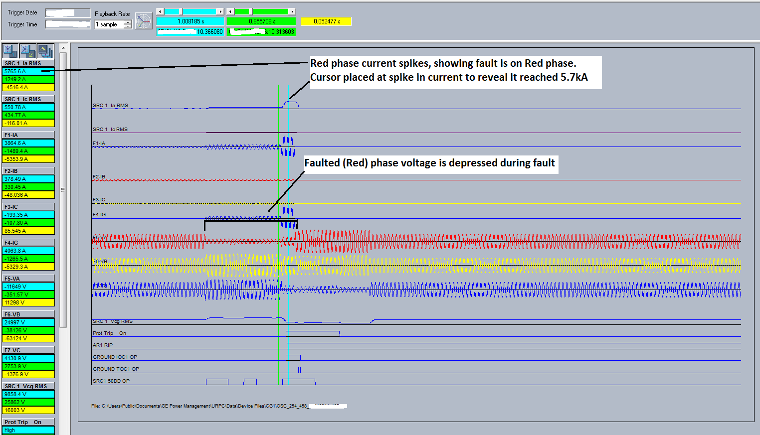
I downloaded the relay oscillography to get a better picture of the fault. The first oscillogram showed the rms earth fault current reached 5.7kA.
The wind farm 33kV collector system contains cables and overhead lines and is impedance-earthed. The typical earth fault is consistently between 1.1kA- 1.8kA. The impedance of the 33kV earthing transformer at the substation is larger than the other impedences influencing the fault level being:
- Impedance of the conductors between the substation and the fault
- The fault impedance
- The return path impedance (back to the earthing transformer) via buried copper earth conductors, overhead earth wires and the ground. The ground impedance varies based on the moisture level
Due to the impedance of the earthing transformer, it is theoretically not possible for a 33 kV earth fault to exceed approx. 3kA on this wind farm.
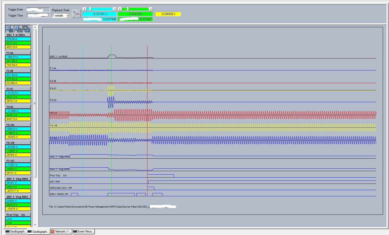
CG1 Oscillography
Oscillography from Collector Group 1 (CG1) feeder protection relay as viewed in GE’s Enervista.
Closer examination of the oscillography revealed the fault was initially at the expected earth fault level of 1.2kA. It then developed into a more solid fault:
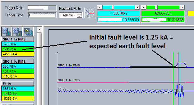
It appeared from CG1 oscillography that a “normal” earth fault developed into a very high-current earth fault, exceeding the maximum theoretical 33kV earth fault level of the wind farm.
Analysis of CG2 Oscillography
The oscillography generated by the CG2 (second to trip) feeder protection relay yielded additional information:
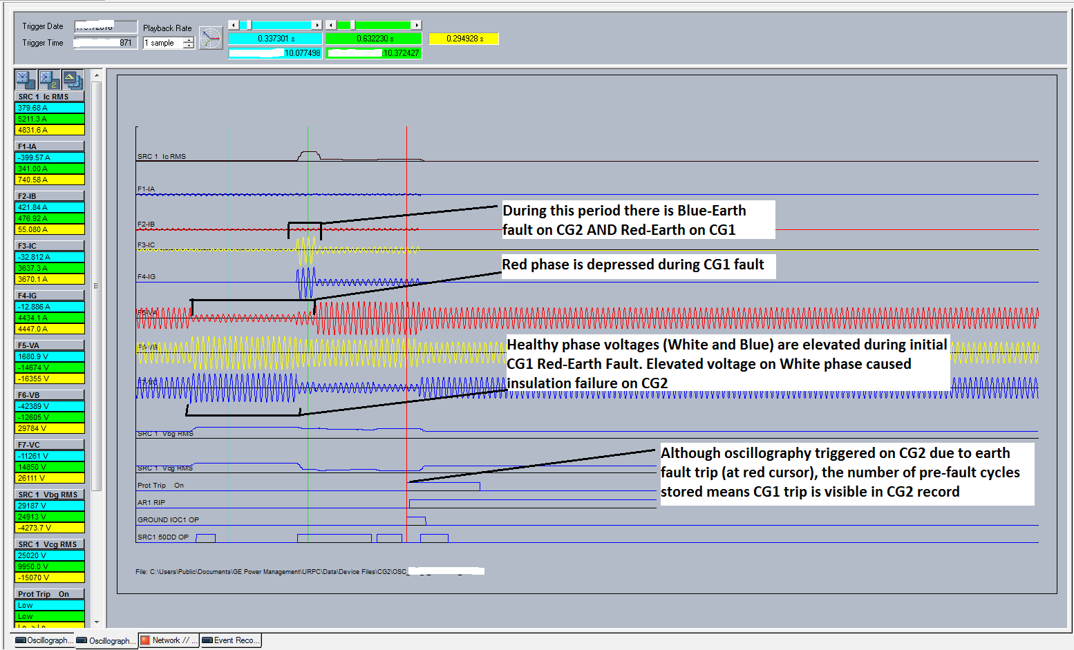
Oscillography from Collector Group 2 (CG2) which tripped ~300ms after CG1
Because of the impedance earthing arrangement, for the duration of the initial Red-earth fault on CG1, the two un-faulted phase voltages rise across the whole wind farm (including CG2) to almost the nominal phase to phase voltage level. This causes stress on insulation and increases the likelihood of insulation breakdown on the un-faulted phases (White and Blue). Consequently, CG2 suffered insulation failure on Blue phase.
Finally, this explains the unexpectedly-high “earth” fault level that was recorded. In the time that the earth faults were simultaneously present on CG1 and CG2 (prior to CG1 CB tripping) there was a Red phase to earth fault and a Blue phase to earth fault. Two phases were faulted to earth. Due to the low impedance earth path between the two faults, it was essentially a phase to phase fault across different feeders. This caused a high fault current in each phase as the current was not limited by the earthing transformer. Because this fault path through earth was downstream of the CG1 and CG2 protection CTs, each protection relay saw an earth fault.
The cause of the initial earth fault on CG1 was likely bird strike, as the collector group was able to be re-energised following the fault. The insulation breakdown on CG2 was a failed 33kV cable termination, which required replacement.
To ensure protection relays capture the event in full and it is able to be easily understood, refer to Protection Relay Configuration to Ensure Useful Fault Records.