

When connecting new wind farms, the utility may impose voltage control requirements at the point of common coupling (PCC). After witnessing voltage control scheme issues, I have compiled the below to assist in planning or auditing voltage control strategies.
A wind farm configuration which includes a STATCOM (e.g. AMSC’s DVAR, ABB’s STATCOM or S&C’s DSTATCOM) is discussed. However, much of the discussion is equally applicable for wind turbines with integral STATCOM-like functionality.
Wind Farm Voltage Control Strategy Should be Driven by Highest/Lowest Phase Voltage, not Average/Positive Sequence Voltage
A voltage control strategy should present a coordinated effort to maintain the grid operating voltage within limits.
The possibility of voltage imbalance must be considered both in regards to transient support as well as steady state operation.
- Transient: e.g. injecting reactive power to prop up the network during a fault. Reactive power should be injected on a per-phase basis (negative sequence control). The faulted phase should receive the majority of the control effort.
- Steady-State: voltage imbalance should be considered, particularly on a weak network. I have seen nominal 66kV systems operating at 70kV with >1kV difference between max and min phase. If the voltage control effort is controlling to the average/positive sequence value, the maximum phase may approach overvoltage trip level.
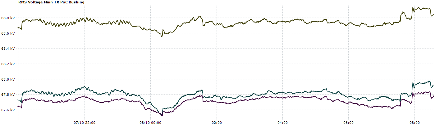 Example of voltage phase imbalance: L12 is 68.7kV while L23 and L31 are almost 1kV lower at 67.8 kV.
If there is significant voltage imbalance on the network, consideration should be given to addressing it (e.g. by phase transposition). Balancing the phase voltages can improve LVRT/HVRT performance of the wind farm by increasing the margin between under and overvoltage limits. Keeping phases balanced may also reduce steady state control effort and I2R losses from excessive reactive power. Additional benefits include running the STATCOM cooler (reducing the likelihood of failure) and reducing current asymmetry at the wind turbine terminals.
Note that it is inefficient to use a STATCOM to address steady state negative sequence voltages. If phase transposition does not improve the issue, consideration could be given to modifying tap positions on existing reactors or somehow otherwise selectively modifying the impedance on a per-phase basis.
Keep in mind that it may not be possible to balance current, voltage and power. Judgement must be used in determining which (if any) require improvement.
Coordinate Voltage Control Efforts
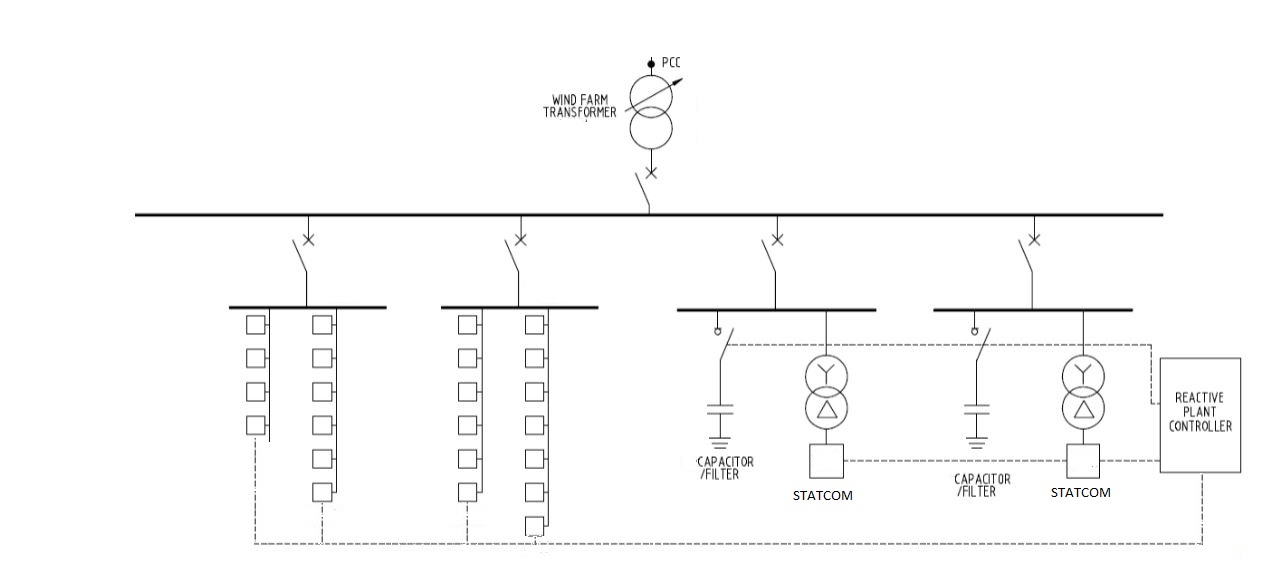
A common configuration for voltage control is a STATCOM connected to the medium voltage bus (via transformers) and controlling the PCC. The STATCOM also commands medium voltage static reactive plant (e.g. capacitors and reactors) and sends reactive power setpoints to the wind turbines to achieve steady state requirements.
 All plant should work together to control voltage at the same location – the PCC. This is where the compliance requirement is. Complimentary control systems should be driven by measurements from the same CTs and VTs (i.e. one set, at the PCC, shared between all controllers).
Examine Wind Turbine Steady State Performance
Whether the wind farm runs in voltage or power factor control, it is usually optimal (considering load flow and redundancy) to share the control effort. Wind farms connected to weak grids can encounter overvoltage issues at the connection point as their power output increases. To counteract this issue, the wind farm may absorb an increasing amount of reactive power as active power increases. If 100% of the voltage control effort is concentrated in one location (for example at 33kV reactive plant) and there is a fault, the wind farm may lose 100% of its voltage control effort and drive the connection point over or under voltage.
Examine Wind Turbine LVRT Performance
If the wind turbine is configured to inject reactive power upon detection of a fault, insure that its effort is coordinated with the PCC requirement. For this purpose, it is particularly useful to have an Elspec meter installed on one MV feeder. It is critical that the measurement devices are time-synchronised otherwise fault-finding can become difficult. Carefully examine the reactive power from the wind turbines prior to, during and post-fault.
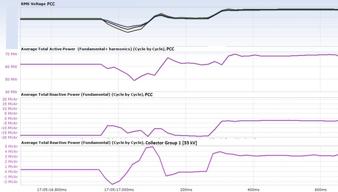 In the above image, it can be seen that the reactive power of the wind turbines on Collector Group 1 is not coordinated with the overall requirement:
- Pre-fault: The turbines on Collector Group 1 (typical) are net exporters (slightly) of reactive power. At the same time, the medium voltage reactive plant is absorbing reactive power (as seen by reactive power import at PCC). Overall, in steady state, the wind farm must consume reactive power in order to control excessive voltage at the PCC.
- During the fault the turbines and reticulation initially consume some reactive power. By the time the turbines/reticulation is injecting reactive power, the voltage is already recovering.
- Following voltage stabilisation, the turbines are injecting significantly more reactive power compared to their pre-fault level. While the intention is to support the grid voltage in response to the dip, this support comes too late and in fact drives the PCC voltage too high. Compare pre-fault PCC volts to post-fault level in the top plot. This turbine response is not coordinated with the overall voltage control scheme. It risks causing an overvoltage trip due to excessive reactive power export. This particular issue of post-fault reactive power injection was addressed as soon as it was discovered via a parameter change disabling the reactive power injection feature.
Consider all Devices which can Affect Voltage
Large loads and harmonic filters can cause significant decrease/increase in voltage when they are switched into service. Control of such devices must be coordinated with the overall voltage control scheme. For example, as a minimum, harmonic filters should be inhibited from switching into service if the PCC voltage is approaching the upper limit. They should be switched out of service at a level well below the wind farm overvoltage trip setting. In a perfect world, the wind farm should always maintain harmonic compliance. But when the choice must be made between a period of potentially non-compliant harmonics and tripping off, remaining connected should be the priority.
On-load tap changers (OLTC) regulate the medium-voltage bus, while reactive power voltage control schemes often take setpoints from the network service provider and control the voltage at the PCC. Potential interaction of the OLTC and PCC voltage control loops must be considered.
All devices which have a significant effect on voltage, should log their operating events to the wind farm SCADA system so that their status can be known when reconstructing the sequence of events prior to a grid event. It is critical that all devices logging events to the SCADA system are correctly time-synched, otherwise fault-finding is extremely difficult.
Do not Contribute more than the Bare Minimum Voltage Control Effort
Wind farms in Australia are overused by network operators for voltage control. If the network operator sets an unattainable voltage control setpoint, consider whether the full reactive control capability should be expended to try to attain it. The generator connection agreement states a range of reactive power the wind farm is required to absorb/consume to assist the network operator’s voltage control efforts.
Contributing more reactive power than required is inefficient and can cause the STATCOM to operate at a level which increases its operating temperature and decreases its reliability. By the same reasoning, take advantage of allowable tolerances to minimise control effort while remaining compliant.
Operate STATCOMs at 0MVAr Output During Steady State Conditions
STATCOMs, like all power electronic devices are more likely to break down as their operating temperature increases. As their primary purpose is grid support during a fault, it makes sense to reserve them for this task. As such, static reactive devices (capacitors, reactors, wind turbine reactive capability) should provide the entire steady state reactive control effort.
Suitable deadbands should be selected to ensure that the STATCOM does not run continuously trying to control a voltage or power factor setpoint very tightly.
Understand the STATCOM Parameters
Most STATCOMs inhibit their output if a fault is particularly deep. As reactive power is the product of volts and amps, if the grid voltage is very low, little reactive power can be injected into a fault. The STATCOM would provide minimal help during the voltage nadir. It is important to understand the VINHIBIT level as well as the basis for its measurement. Is the output inhibited if a single phase falls below 0.x p.u. or if the positive sequence voltage falls below 0.x p.u?.
Examine STATCOM Logs Following Voltage Dips
It should be possible to download fastlogs/snapshots/oscillography from the STATCOM SCADA system following a voltage event. Check the response of the STATCOM to ensure the direction of reactive power flow is always driving the PCC voltage in the required direction. Additionally, ensure that the reactive power injection occurs before the voltage starts to recover. The STATCOM does not provide much value if it only starts trying to boost the grid voltage when it is already naturally recovering (i.e. the fault has cleared).
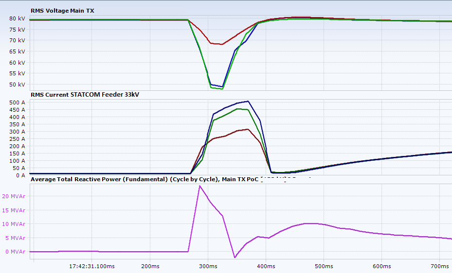 In the above plot, the STATCOM is quick to react to a voltage dip on the network. It rapidly injects capacitive reactive power to boost PCC voltage. It then reduces the reactive power injection so as not to cause voltage overshoot following recovery.
STATCOMs (and many inverter systems) are susceptible to DC bus overvoltage alarms (and damage). Assess how close the STATCOM is getting to its DC bus overvoltage trip limit following fault recovery. Consider configuration changes that might mitigate the risk of tripping following a worst-case voltage recovery scenario.
Ensure the Voltage Controller Remains Operational in the Event of a STATCOM Trip
If the STATCOM trips (e.g. on DC link overvoltage or inverter failure), it is important to ensure that it continues controlling the remaining reactive plant. For example, if the STATCOM has medium voltage reactors under its control, these should not trip on STATCOM failure. They should remain controlled, albeit without soft-switching from the STATCOM. This sounds obvious but it has caused issues.
In the case of STATCOM failure (including the master controller), this is another reason to spread the voltage control effort across multiple devices (e.g. wind turbines). This avoids simultaneous loss of the entire control effort. The wind turbines must default to a safe voltage control setpoint on failure of the master voltage controller.
Use the Lowest Gains that still meet Performance Standards and fall inside Protection Settings
At higher power output, small changes in reactive power can cause large changes in voltage at PCC. This is particularly true for wind farms connected to a weak grid. High control loop gains coupled with a weak grid connection is a recipe for voltage instability. Lean towards low gains. Examine the performance of the STATCOM following grid events to determine whether it meets the generator performance standards.
Minimise Measurement Delays
If the wind farm is ever constrained according to the voltage on a remote bus, avoid signalling arrangements from the NSP like “reduce voltage”. These are subject to unknown device polling times and delays. Slow measurements are a recipe for instability. Request the raw measurement of each phase rather than a three-phase average (considering the above-mentioned imbalance possibilities). Ensure the update rate (DNP3 deadbands etc.) is sufficiently fast.
Conclusion
Careful design of a coordinated wind farm voltage/reactive power control scheme will increase the likelihood of successfully riding through a network fault.
Consider and coordinate the response of all devices capable of affecting PCC voltage. Designs featuring redundancy will be more robust. If any single piece of equipment fails (or CB trips), some voltage control effort should remain.
Do not limit wind farm performance analysis to wind turbine SCADA data analysis. Continuously examine the response of your wind farm voltage control scheme, both in the steady state and following grid events. Proper commissioning of all recording and logging devices will make fault-finding much easier. It may be the difference between proving your plant compliant or receiving a notice of non-compliance.
Parameters are rarely optimal on the first pass. Parameters should b reviewed frequently as changes may improve fault-ride through or steady state performance and reliability.